Convolutional (Faltung) Codes |
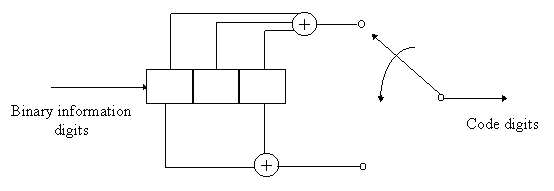
A simple rate ½ convolutional code encoder
is shown below.
 |
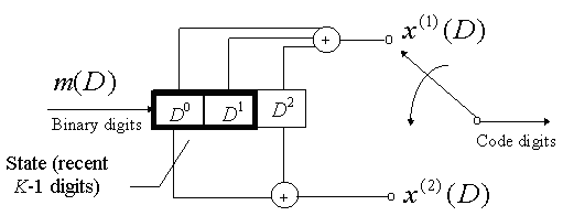
| The rectangular box represents one element of a serial shift register. The contents of the shift registers is shifted from left to right. The circle with a plus sign inside it represents XOR operation. Notice how the code digits which are output by the encoder are multiplexed into a serial stream of binary digits. For every binary digit that enters the encoder, two code digits are output. Hence code rate = 1/2. |
The constraint length K of a convolutional code is defined as the number of shifts over which a single message bit can influence the encoder output.

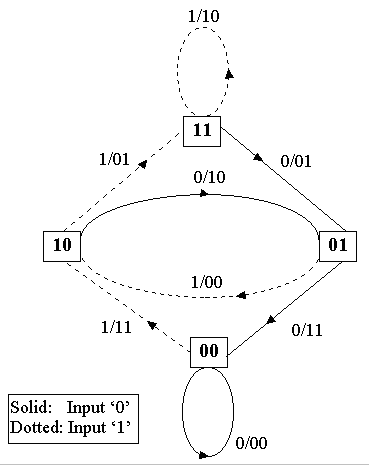
| INPUT DIGIT | INTIAL STATE | FINAL STATE | OUTPUT CODEWORD |
| 0 | 00 | 00 | 00 |
| 1 | 00 | 10 | 11 |
| 0 | 01 | 00 | 11 |
| 1 | 01 | 10 | 00 |
| 0 | 10 | 01 | 10 |
| 1 | 10 | 11 | 01 |
| 0 | 11 | 01 | 01 |
| 1 | 11 | 11 | 10 |

KEY
1/01 This means for example, that the input binary digit to the encoder was 1 and the corresponding codeword output is 01.
![]() This represents the state of the encoder. In this example, the state
is 01.
This represents the state of the encoder. In this example, the state
is 01.